ETX-70AT focuser extension, take two.

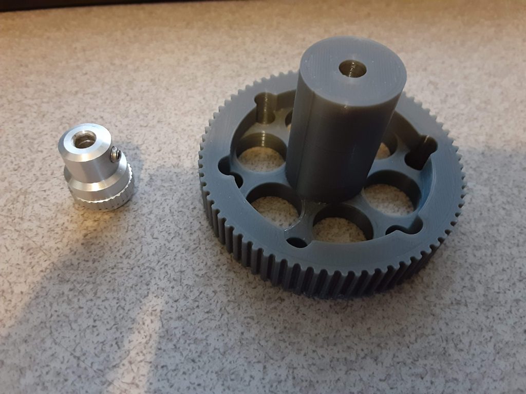
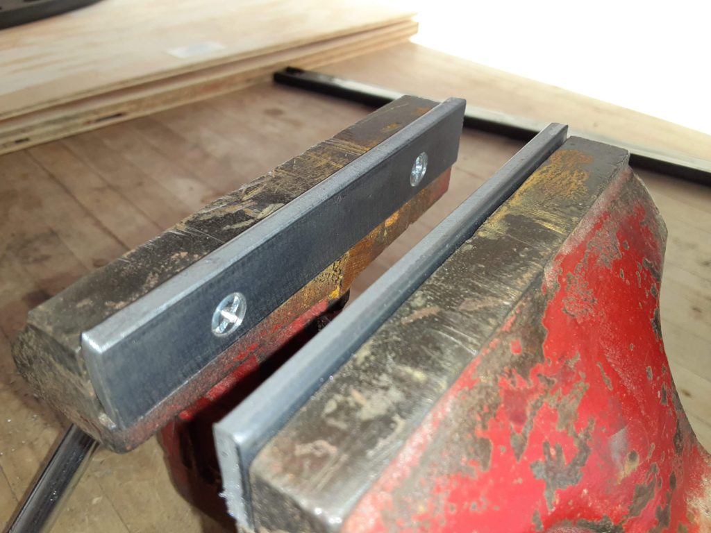
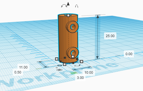
Not wanting to drive back down to Ace, I started rummaging through my junk pile to see if there was anything I could use to fabricate a new coupler to replace the aluminum spacer I had tried to use. I looked at some 1/2″ steel bar stock I have, but decided I really need a lathe to make that work like I want, so I continued to rummage. I happened to run across a block of HDPE that I had made by melting down plastic milk cartons, and decided maybe I could cut and drill a chunk of that and make it work. As I secured it in the vise and started looking for a saw, it occurred to me that if I was going to make one out of plastic, why not 3D print it? So off to the computer, and I spent about 5 minutes in TinkerCAD to come up with this:

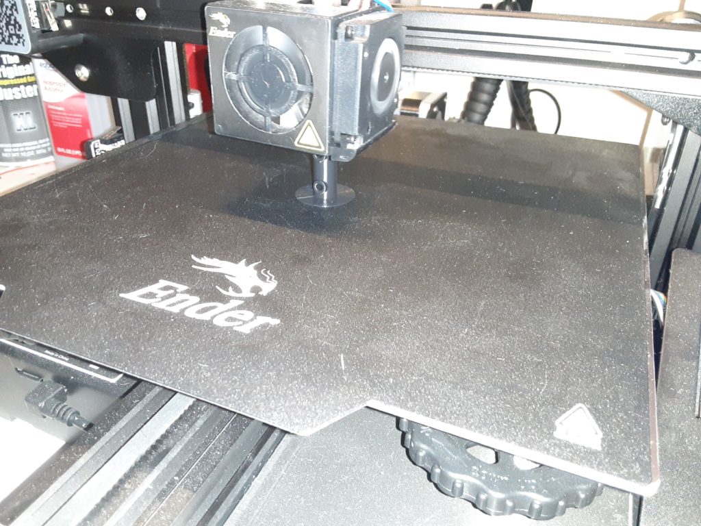
I sliced it in Cura and set it for 100% infill to be sure I’d have enough thickness to cut threads into. At $20/kg, Cura tells me this piece is going to cost the princely sum of 5 cents, even with all that infill. I also kicked the print temperature up to 210C, as that will supposedly result in a stronger print. Sent it over to the printer, and 30 minutes later, I have a part:

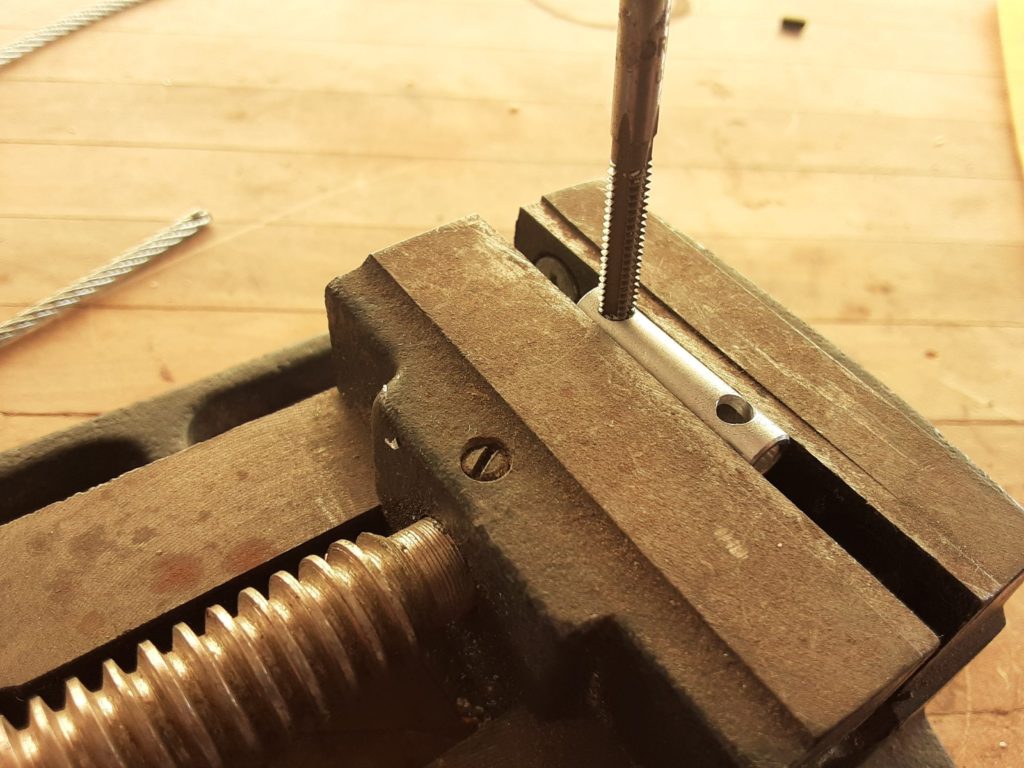
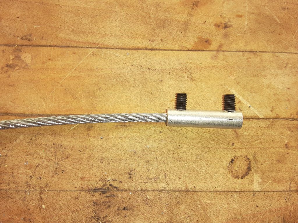
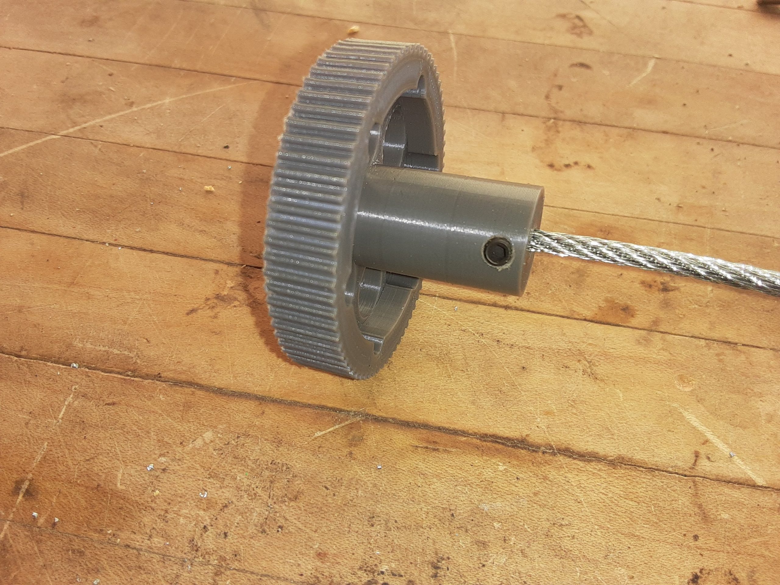
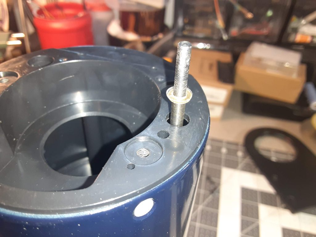
When I designed it in TinkerCAD, I used 3mm holes for the setscrews, thinking I would drill them out, then use the tap, but I ended up tapping them both without bothering to drill it, and it worked great. I carefully threaded the setscrews in, and cinched them down on the cable and focus rod:

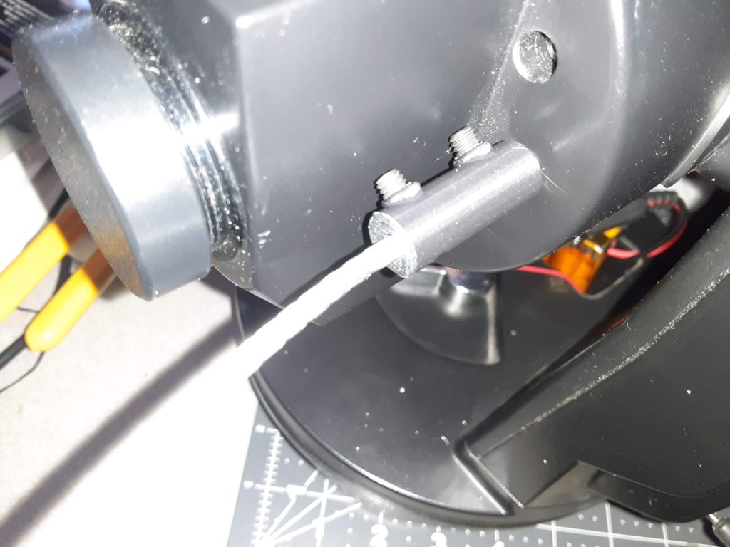
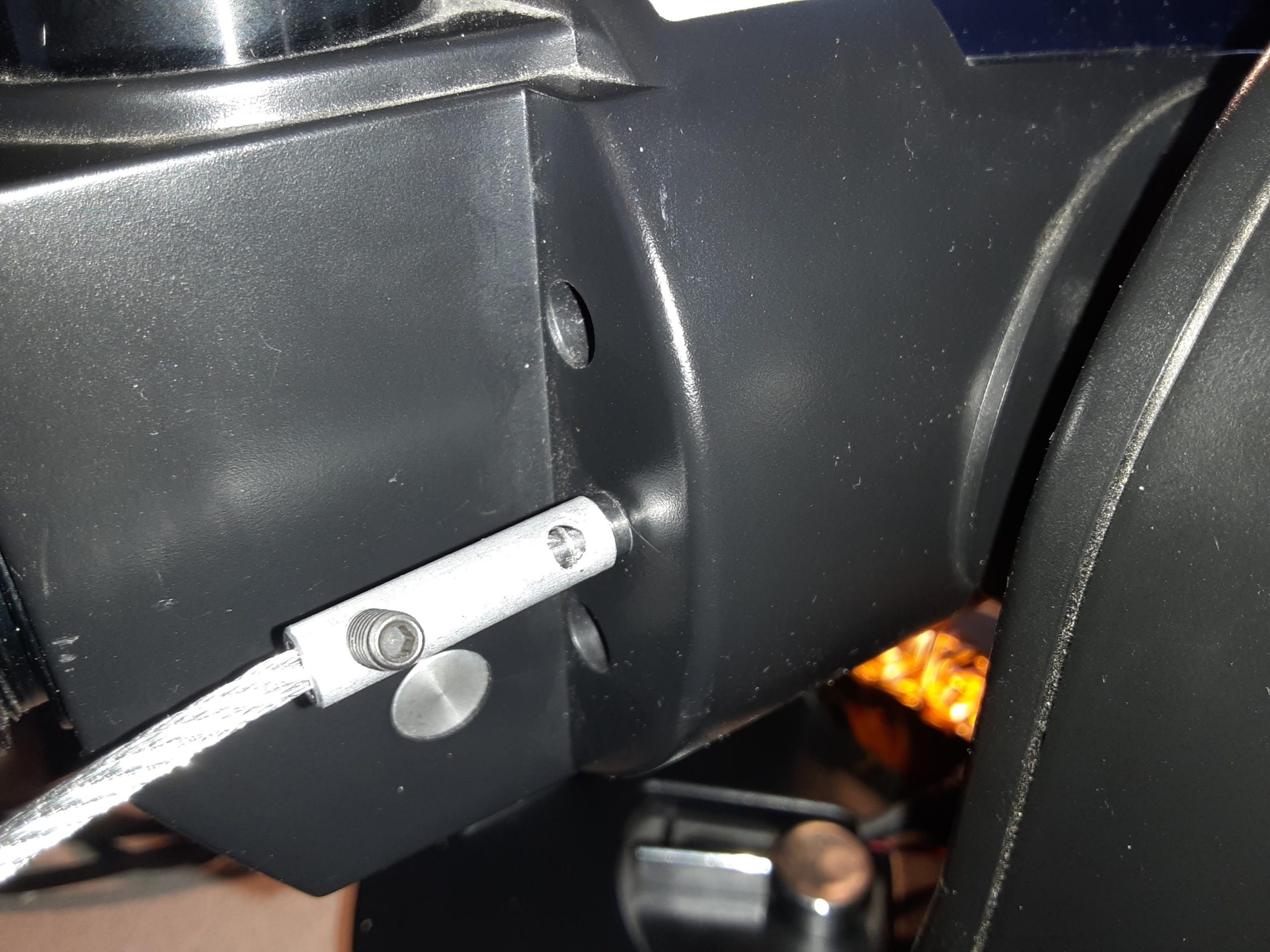
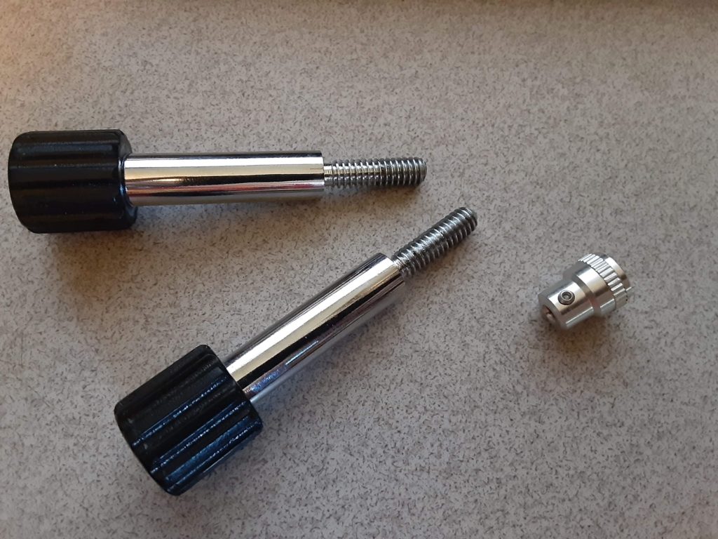
Gave the knob a few test spins, and the objective lens is now focusing smoothing in and out. Here is the finished extender:

ETX-70AT focuser extension, take one.

So I attempted to to build a flexible focus extender for the ETX-70AT telescope. The concept is solid, and the price is right but mistakes were made.

I spent a grand total of $2.42 at Ace for an aluminum spacer, a foot of cable, and some set screws. As I drilled and tapped the holes in the spacer, mistakes #1 and #2 became evident.

I had selected #8-32 set screws, just because I already had a tap for #8-32. It was quickly apparent that this was way too big for this particular spacer. I could also see that I probably should have gone with a steel spacer rather than aluminum, so the threads would be stronger, as there turned out to be very few of them. The set screws are also waaay too long, as you can see here:

The long set screw worked beautifully in the knob, however. I had printed the knob with 20% infill, so the tap was only making threads on the inner and outer walls. I probably should have modified the STL file to include a hole to tap, or just printed it with 100% infill, but the set screw was actually just long enough to grab the few threads that were there, and get a nice solid bite on the cable.

Despite the mistakes that’d I’d encountered, it was shaping up nicely, until I tried to attach it to the focus rod on the telescope. The few threads I was able to catch before the set screw hit the rod just peeled right out of the spacer because the aluminum was too soft.

Debating at this point about either redoing the spacer in steel with smaller set screws, or using a file to create a flat spot on the focus rod. Or maybe both…

The myth of the so-called “Safe Place”

Several weeks ago I removed these three items from the Meade ETX-70AT telescope in preparation for tearing it down:

That’s the focusing knob, and the tripod bolts. I put them in a “safe place” so they would not get lost, but once I got around to tearing the telescope apart and putting it back together, do you think I could find them? Spoiler alert: No, I could not find them.

I’ve spent countless hours over the past week looking for these, only to come up empty handed each time. Then this morning, as I looked for a completely different item, there they were, sitting in a drawer I had looked in at least three times. Never fails. I spend more project time looking for things I know I have than I actually spend on the project itself.

Every. Damn. Time.

So back to the project… Over the course of that week, I decided that the stock focusing knob has two fundamental flaws that needed to be addressed. First off, the knob is just way too small, which makes fine focusing difficult. Secondly, it’s right up on the back of the telescope next to the eyepiece housing, and gets harder and harder to get at as the telescope is pointed higher. In fact, it is impossible to get at when the telescope is anywhere near straight up.

I have a two part plan to alleviate this. First is a replacement knob which I 3D printed from an STL file I found on Thingiverse:

As you can see, it has a much larger diameter which should make fine focus much easier. This particular knob was designed for the ETX-125, and is actually too big for the ETX-70, as the eyepiece housing is in the way, but that’s OK as it leads right into part two of the plan, which is a flexible shaft extender which will move the knob out past the eyepiece, and should make focusing easier when in vertical orientation. There’s a guy selling one on Amazon for $9.98, but I’m thinking I can fabricate one for much less after a visit to my local Ace Hardware.

To be continued….

ETX-70AT Teardown

More telescope fun. I have an Meade ETX-70AT telescope that I got at a pawn shop for $15. It was missing the battery pack, eyepieces, and the focuser seemed jammed. Since I have eyepieces that fit it, and the focuser seemed like it might be an easy fix, I naturally bought it and brought it home.

I built a 12v battery pack for it, but found the handset connection seemed to be intermittent, and when the handset did come on, it showed a “Motor Unit Failure” error. I opened it up and verified the motors were not bound up and none of the gears appeared to be stripped. Some of the ETX message boards online suggested making sure the encoders were not blocked with grease or other debris, so I checked this as well. While the main circuit board was exposed, I also checked it over, and reflowed some of the solder joints that looked sketchy. Still getting the MUF error after getting the handset to come on. Hmmm.

Giving up on that for the time being, I moved on to the optics, and pulled the primary lens and focusing rod out.

The issue with the focuser turned out to be a little washer on the focusing rod. It is supposed to ride on a step in the rod, but it had gotten pushed over the step and further up the rod. I removed it, and smacked it with a hammer a few times to flatten it back out, and now it sits properly on the step. The focus seems to work, other than the fact that I lost the focusing knob somewhere during all this. It’s just as well, the knob is in a very awkward place, and I am planning to extend it out with a flexible shaft anyway.

While putting the telescope back together, I did some more troubleshooting on the electronics, and found that the MUF error only comes up if the power is on when I fiddle with the handset connection to get it to come on. By wedging the connector with a screwdriver, and then turning the power on, the system boots up normally, and goes into the alignment mode, and then will attempt to seek to whatever object is selected.

Now I just need to work on the focuser extension, and figure out some kind of mount or tripod for it. Oh, and figure out something better than a screwdriver to wedge the handset connection with.

Mini Dob update

Fairly clear skies last night, so I took the Dob out for a test viewing. I found that the bolts I was worried about hitting when adjusting the telescope up and down were the least of my worries. I think they only hit once or twice, and even then they weren’t too jarring because the glides are rounded, and I used an angle grinder to cut the protruding all-thread flush with the nuts, so it’s not bad at all. There does need to be a bit more friction there, however, as the telescope would tend to drift down on its own when at low viewing angles and one of the heavier eyepieces in. All in all, though, altitude adjustments are not a problem.

What was a problem is the azimuth adjustment. Remember those felt feet that felt right? Nope. WAY too much friction, even with the wing nut backed all the way off. So much so that trying to guide the scope by holding the optical tube would sometimes yank it right out of the rocker box, so I’d have to hold on to the rocker box to get the azimuth changed, and it was a bit herky jerky. Very frustrating.

Adding to my frustration was the fact that I thought I’d be clever and pull the other scope out, and hook it up to a web cam and a laptop to see if I could do some astrophotography. For some reason the webcam and this laptop will only talk to each other intermittently, even though the web cam works fine on the desktop PC. Grr. And every time I’d look at the laptop, my night vision would get ruined due to the brightness of the screen.

Lessons learned:

  1. Pay attention to what other telescope builders are doing. If they are all using Teflon and/or milk jug washers, go with that, at least for a first attempt. There is probably a reason none of them are using felt for the azimuth turntable.
  2. Stick to one new technology at a time. Trying to work out quirks in the Dobsonian mount, *and* trying to troubleshoot webcam issues at the same time just lead to increased frustration.
  3. Get some night vision friendly lighting. Between using my cell phone as a flashlight and looking at the laptop screen, my eyes never did adjust to the dark, or at least what passes for dark here in the city. I did later setup a night vision theme on the laptop, all reds and blacks, so that will help when using it, but I still need a light source for picking up dropped lens covers, and sorting through eyepieces.
  4. Keep a star chart handy. I have Stellarium on both the laptop and my tablet, but did I use either one? No… I was attempting to find the Orion Nebula, and I know right where to look, but even zoomed out with the 26mm eyepiece I was getting lost due to the fact that I was seeing so many more stars through the telescope than I was with my naked eye. Being able to compare the telescope view with the star chart should help me get reoriented. Of course it didn’t help that I was unable to smoothly track back and forth due to the aforementioned azimuth friction issue. That will be addressed….

4.5″ Mini Dob Project

I have a 4.5″ Newtonian reflector telescope that I got for $10 at a local thrift store. The views are OK, but the dovetail mount to the tripod is super wobbly, and the thing will shake if you even breathe on it, so I decided to build a Dobsonian mount for it.

I designed some telescope rings in Tinkercad, and 3D printed them in PLA. I used JB Weld to anchor some 1/4-20 all-thread in them, which was in turn used to attach the rings to a scrap of plywood and a 4″ PVC cap, which will serve as the altitude bearing.

I made the mistake of deciding to leave the dovetail mount attached to the telescope, which meant the rings needed to straddle it, causing them to be attached outside the bearing surface rather than inside as I had intended. This would cause issues later (The PVC bearings ride on some small felt furniture glides, and there is enough slop that some times the bolts will hit the glide as the scope is raised or lowered. This would have been totally avoided if the ring bolts were inside the bearing. I may just 3D print some guides to keep it from slopping and mount them on the outside edge of the rocker box. Depends on how often the bolts actually hit with the scope in use).

With rings and bearings attached, I could now measure for and construct the rocker box and ground board, which were both made from some left over plywood I had sitting around.

Couple coats of Flat Black paint, and it’s starting to look like something.

For the azimuth turntable, I mounted an old LP to the ground board, and felt furniture feet to the bottom of the rocker box. Fittingly, since I was doing this over the Christmas holiday, the sacrificial LP was “Ira Ironstrings Plays Santa Claus.” Sorry, Ira, but you were pretty scratched up. Many amateur telescope makers use Teflon here, but felt just, uh, felt right (no pun intended).

On the inside of the rocker box, I secured the ground board to the rocker box with a fender washer and a wingnut, so the amount of friction on the azimuth turntable is adjustable. The felt furniture feet are also adjustable, but that’s not a design feature, it just happened because the feet I had on hand had threaded inserts and I doubt I will ever adjust them.

I added a carrying handle to the front of the rocker box, and a 3D-printed eyepiece holder to the back.

Rubber feet on the bottom of the ground board completes the project. Now just need some clear skies.

DIY Spot-welder, part 2

Found some lugs, found the starter relay, and cut one of the leads from the secondary to hook it up:


Next I started looking at the control board, and it occurs to me that I want all of this stuff in an enclosure of some kind, but I need to be able to access the board if I need to adjust the length of the pulse. Problem is, it is not suited for panel mounting at all:


Rooting around in my junk drawer, I found a bit of left over plexiglass that I can mount the control board to using some standoffs:


After taking some measurements, I started crafting an enclosure from some thin plywood. All I can say is I am in no way a woodworker. Good thing this is for utilitarian purposes rather than decorative:


Got some holes drilled and a cutout for the display and did a test fitting:


I had intended to just hot glue the plexiglass behind the cutout, but I found the display looked better when the plexiglass was outside the enclosure, so I think I’ll trim it down to a thin frame, and just superglue it on the outside.

DIY Spot-welder, part 1

I’ve watched a bunch of YouTube videos on the subject, narrowed my approach down to two methods, and I may end up building both. One involves a rewound transformer salvaged from an old microwave oven, and the other a really big capacitor. I already have the transformer, so that’s where I will start.

Step one involved pulling the transformer, and rewinding the secondary on it. Microwave transformers are built with many more turns of wire on the secondary than on the primary, so as to increase the voltage many-fold to run the magnetron. For my application, the secondary needs to be replaced with a low number of turns of heavy gauge wire, which should lower the voltage, but increase the current. I used a hacksaw to cut the weld on the transformer core, separated the two halves, and gently extracted the primary, the secondary and the magnetic shunts. I then wound three or four turns of old jumper cable around the core, reinserted the shunts and the primary, and used JB Weld to secure the two halves of the core to each other:


For the electrodes at the end of the cables, I soldered on halves of some sort of probe clamp I got on the cheap from the surplus store (EE Surplus, to be exact, that place is awesome).

Now a word about this particular jumper cable. It got replaced because it wasn’t working very well as a jumper cable, and on a couple of occasions the insulation started melting while trying to jump start my truck, and I was afraid it was going to catch fire. When I cut into it for this project, I saw why. The actual gauge of the wire is fairly low, and the cable thickness is mostly insulation. Whotta rip-off! Anyway, this left me concerned that it was not going to be able to develop enough current in this application to actually spot weld anything, but my test welds revealed that there was plenty of current, and was actually blowing holes in the nickle strips:


I was able to get some welds that actually stuck to the battery by making the contact time as short as humanly possible, but it was hit or miss. What I need now is some way of controlling the current flow in a precise manner. Luckily, in one of the YouTube videos I watched the guy was having this very same problem, and he solved it by using an automotive starter relay that he controlled with a microprocessor that could be set for very small units of time. Well it just so happens that I bought one of these relays 35 years ago, never used it, and it has been in the bottom of my toolbox ever since. As for the microprocessor controller, I could build one with one of the Arduinos I have on hand, but to limit the complexity of the project, I jumped on Amazon and just purchased the same on he was using. It was cheap, and they’ve already worked all the bugs out of it. I’ll start figuring out that piece of the puzzle in part 2….

Long time, no post. Still lame!!

Well. Almost two years without posting anything. I’ve been working on projects, honest I have…

Like the clock I found at Goodwill and turned into an old-time internet radio thingy:


And the jaws I built for the jaw-less vise I found for fifteen bucks at the local surplus store:


And my latest obsession is building lithium-ion battery packs from reclaimed 18650 battery cells:


Sharp-eyed viewers will notice something missing. That’s right, the nickle-clad strips that should connect the cells to each other are absent. Why you ask? Well, I seem to lack a spot-welder to attach said strips to the cells. Sure, I could purchase one on Amazon, but this is supposed to be a low-budget project, not to mention I am a tight-wad. So the next project in the pipeline? You guessed it, baby, a DIY spotwelder, crafted from a transformer ripped from the bowels of a dead microwave and, uh, transformed to meet my spot-welding needs and desires. Stay tuned!

My new latest obsession

I’ve had a fascination with radio for ages. My grandpa was a ham radio operator, and would give my brother and I ham study guides and HF receivers to listen to in an attempt to fan the flames of interest. Back then one needed to be able to send and receive Morse code to pass the licensing exam, and neither of us could ever quite master it. By the time the FCC started eliminating the code requirement, I was married and raising kids and had no time. Fast forward many years, and a series of events transpired that rekindled the desire to get licensed. I studied for a few weeks, then went and passed the Tech and General exams on the same night. So now, I need a radio…

I have a little handheld 2M radio to play with, as well as my grandpa’s 2M Heathkit mobile radio, but would like to have an HF radio as well, maybe hook it up to a laptop and play with some of the digital modes. I’ve got a short list of radios I want to look for at the upcoming hamfest, but that’s not until the end of September, and would like something now, preferably without dropping a load of cash. Looking around, I discovered a radio out of India called the uBITX. It’s sort of a kit that you assemble yourself. It’s not quite the level of kit like the Heathkits of old, as the boards are already assembled, tested and tuned. For this kit, I need to provide an enclosure, speaker, and microphone case, mount it all in the enclosure, and solder up all the wires and connectors.

The radio is on the way from India, should be here in a week or so. In the meantime I’m already looking at the large number of modifications that can be done, and I’ve decided the first one I want to do is swap out the 2-line LCD display for a Nextion color touchscreen. The Nextion arrived yesterday, and I’ve already got it flashed with the custom firmware for the uBITX. It’s looking pretty cool, can’t wait for the radio to show up!