ATX Breakout Box

Working on these Arduino projects has left me wanting/needing a bench power supply, but I'm finding those things to be fairly pricey. Watching YouTube one day, I ran across a bunch of people that were hacking apart old ATX power supplies salvaged from discarded PCs, and breaking out the various voltages that are produced. “Brilliant!” I thought to myself. I've got three of them under my desk right now, all of which probably still work, and are capable of giving me 12v, 5v and 3.3v on the cheap. Perfect for what I am doing. The only drawback I could see is that a.) opening up a power supply and hacking up the wires inside is probably not the safest thing in the world, and b.) I'd hate to go through all that work, only to have the power supply crap out on me a couple of months down the road. That's when I started thinking outside the box. Well, outside the power supply anyway, and into a different box: A breakout box.

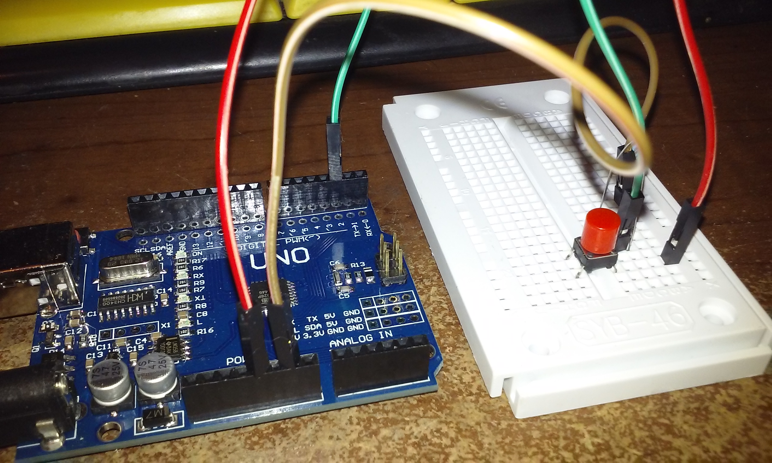
For step one, I scrounged up an old motherboard with a 24-pin ATX connector and desoldered it. All the extra power supplies I have kicking around are 20-pin, but I wanted to have the flexibility of using either. Here I’m testing using a red LED and a 220-ohm resistor on the 5VSB pin, a green LED and a 220-ohm resistor on one of the 5VDC pins, and I’m shorting across PS_ON and one of the COM pins:

Testing the theory
Testing the theory

As I had hoped, the red LED is lit whenever the power supply is connected to AC power by virtue of being connected to the standby pin, and the green LED lights up as soon as the power supply turns on when PS_ON is shorted to ground. Sweet!

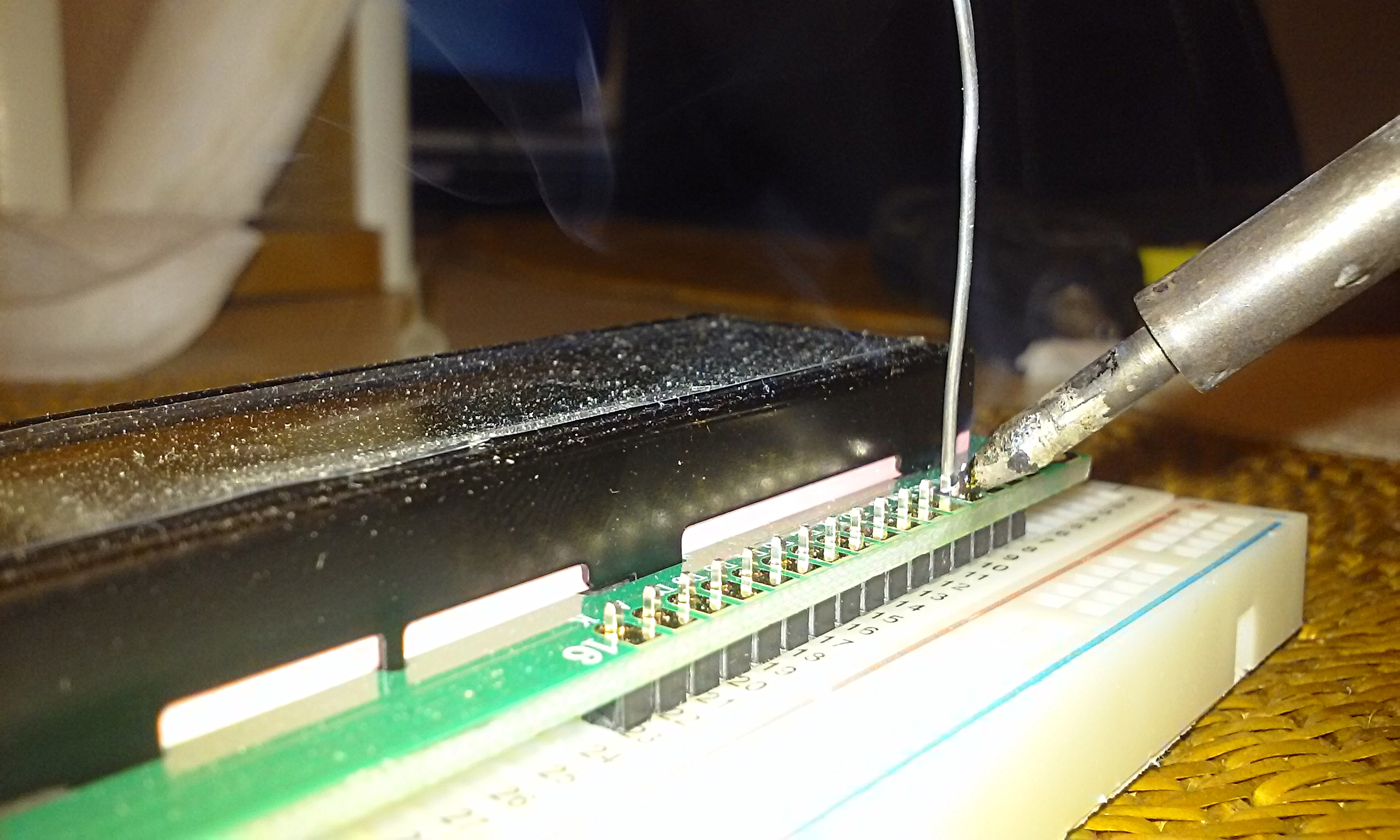
Next I soldered the resistors to the LED anodes and protected them with some heatshrink tubing. Here I’ve got them soldered to the appropriate pins on the ATX connector, and hot glued into place in the project box (the power switch is mounted, but not yet connected):

LEDs in place
LEDs in place

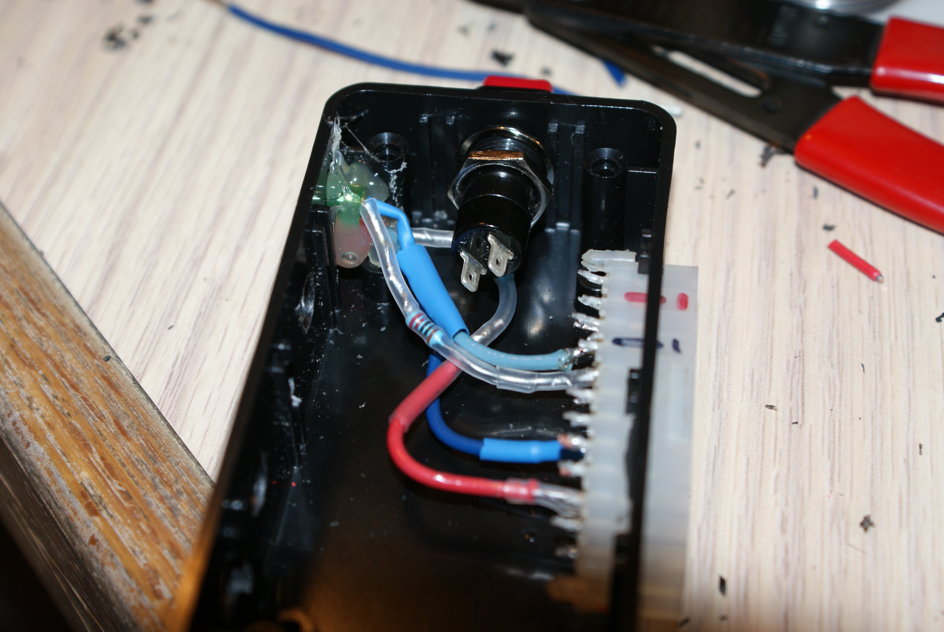
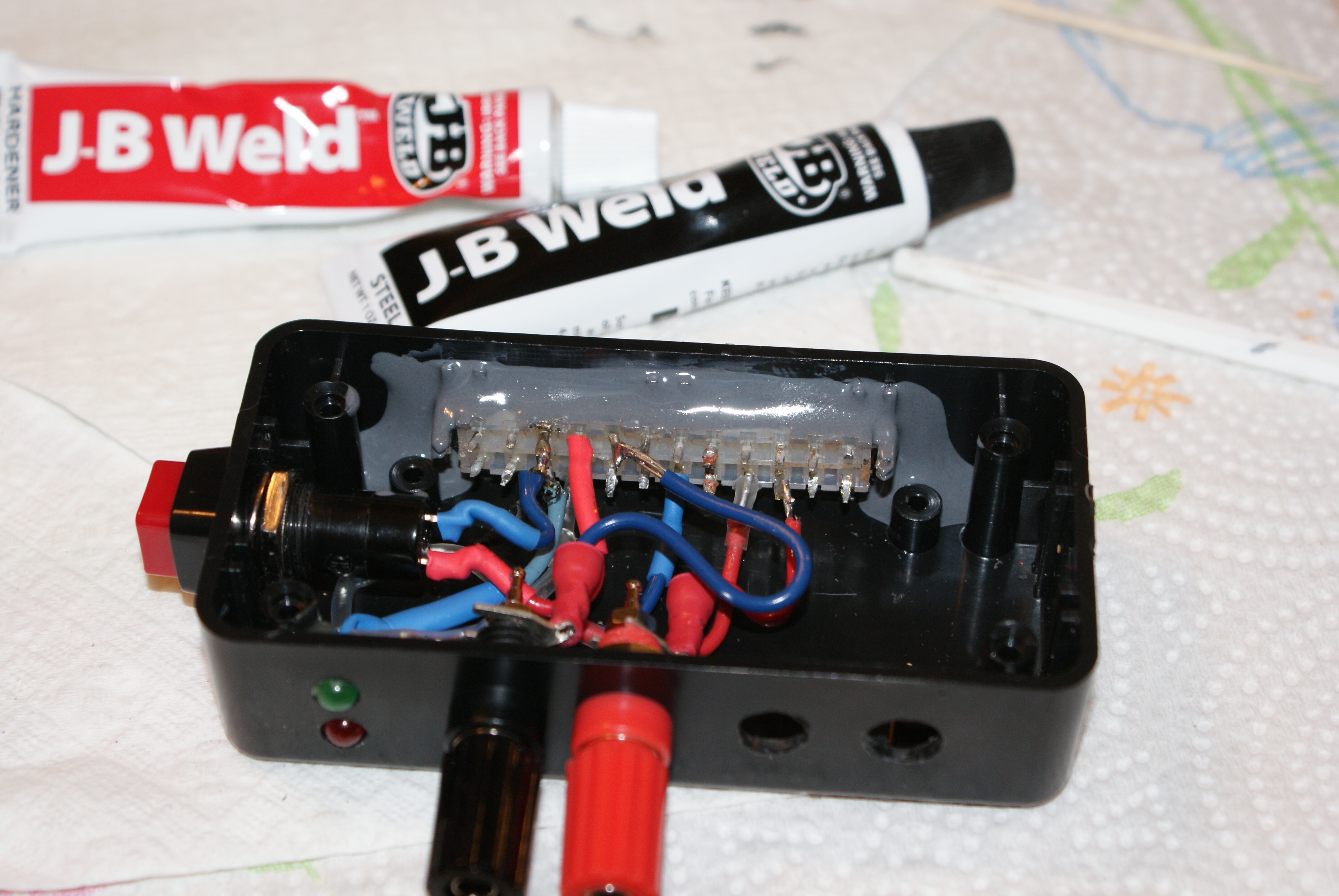
Next I connected the switch and binding posts up to the appropriate pins. For now I am only hooking up the 12v (because the place I got the binding posts at only had two, pfft), but I went ahead and drilled holes in the project box for the 5v and 3.3v posts. I was not sure how I was going to secure the ATX connector, since it really didn’t have any decent mounting points. I racked my brain for a bit, and decided on JB Weld. After all, a farmer in Kansas fixed the engine block on his tractor with it, right? Sadly, that story is no longer on the packaging. They should totally bring that back. But I digress, here’s the JB Weld, slopped in there good:

JB Weld to the rescue

I let that cure overnight, then plugged in the power supply and gave it a test:

Good enough for government work

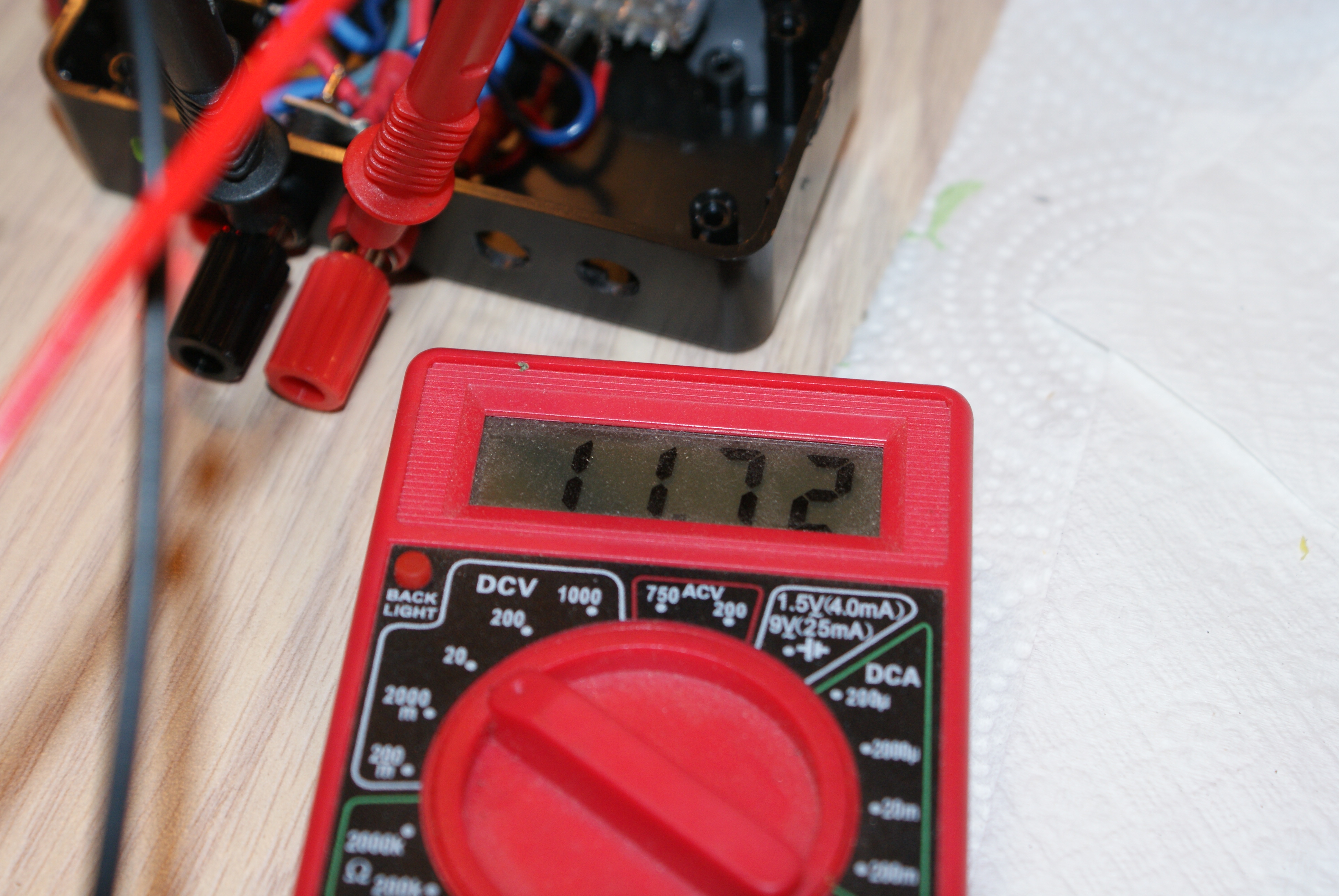
Ehh, close enough for Government work. (An uncle of mine defines that standard thusly: Measure it with a micrometer, mark it with chalk, cut it with an axe.)

Here we are with the box closed up and a couple of labels affixed for reference:

Looking good.
Looking good.

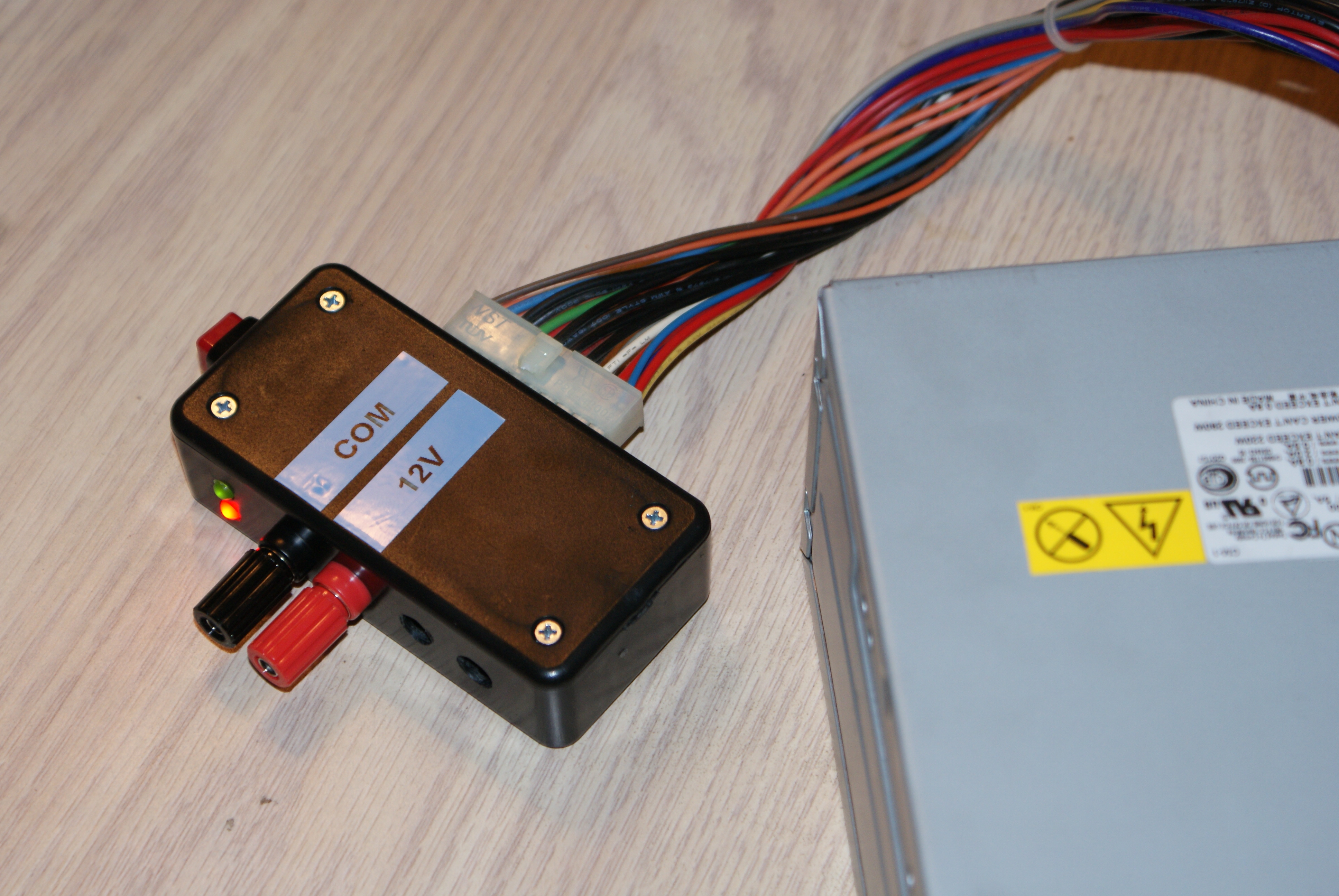
Much safer to use, and if the power supply happens to give out, I can swap it out in seconds. I like it. Now off to find a couple more red binding posts.

Cleanup on aisle 5…

Spent the morning cleaning up the code, changing all the “button” references to “sensor” for that eventual day when I get an actual sensor, and started fiddling about with the other three values that are going to show up on the display, namely system voltage, water temperature and oil pressure. It was in doing these that I realized I was outputting the MPH in reverse. I hadn’t noticed because it was so hard to get a two digit MPH reading mashing on the button. So I fixed that, and streamlined the code a bit. I find that programming for 32Kb of storage really helps you focus on tightening up sloppy code. And man, do I write sloppy code. I am so out of practice. So I created sections for the other three sensors, and just had them generate random numbers in approximately the right range so I could format the output to the display, all while NOT breaking the code for calculating MPH. So far, so good:

Here’s the code as it stands right now:

/*
  Gauges
  
  (Gauges? We don't need no stinkin' gauges)

   Digital gauges for a vehicle that does not have ODB.

 */
 
#include 
LiquidCrystal lcd(12, 11, 5, 4, 3, 2);  // set up the LCD's number of columns and rows

// constants 
const int sensorPin = 8;     // the number of the Hall sensor pin (currently a pushbutton)
const float distance = 23.5;   // distance covered by the vehicle for every revolution of the drive line


// variables:
int sensorState = 0;         // variable for reading the pushbutton status
int old_sensorState = 0;     // variable for pervious pushbutton status
int pulse = 0;               // pulse
int mph = 0;                 // miles per hour
float vlt = 0;               // system voltage
int psi = 0;                 // oil pressure in PSI
int fwt = 0;                 // water temp in degrees F

void setup() {
  
  pinMode(sensorPin, INPUT); // initialize the sensor pin as an input
  
  // Once testing is done, the Serial bits will be removed
    Serial.begin(9600);
    while (! Serial); // Wait untilSerial is ready 
    Serial.println("Ready");
  
  
  lcd.begin(16, 2);
  // Print a message to the LCD.
  lcd.print("Initializing...");
  delay(2000); // wait two seconds
  lcd.clear(); // clear the LCD
  
  lcd.setCursor(4, 0);  // move cursor to column 4 on line 0
  lcd.print(" VLT");     // write VLT
  
  lcd.setCursor(4, 1);  // move cursor to column 4 on line 1
  lcd.print(" PSI");     // write PSI
  
  lcd.setCursor(12, 0);  // move cursor to column 12 on line 0
  lcd.print(" ");
  lcd.print((char)223);  // write the degree symbol (ascii 223)
  lcd.print("WT");       // write WT
  
  lcd.setCursor(12, 1);  // move cursor to column 12 on line 1
  lcd.print(" MPH");     // write MPH
}

void loop() {

  // measure system voltage
  vlt = random(80, 147 )/10.00; // fake it for now
  // end measure system voltage


  // measure the water temp
  fwt = random(97, 195 ); // fake it for now
  // end measure water temp
  
  // measure the oil pressure
  psi = random(6, 12 ); // fake it for now
  // end measure oil pressure

  // measure vehicle speed
  unsigned long startTime = millis();  //get the millisecond count at the start of the loop 
  unsigned long interval = 1000UL;     // set the loop interva1 to 1 second
  
  pulse=0;                             // reset the number of pulses before the next count
  while(millis() - startTime < interval)  //loop for the amount of time set by interval 
  {
  
  sensorState = digitalRead(sensorPin); // read the state of the sensor

 
  if ((sensorState == HIGH) && (old_sensorState == LOW)) {  // If the state has just changed from low to high
    pulse = pulse + 1;                                      // then count a pulse
    delay(10);                                              // and delay for just a bit
    }
   old_sensorState=sensorState;         //set the old sensorState to the current sensorState
  }  
  

  mph = ((pulse * distance)/(interval/1000)) * .0568;  //calculate MPH
    
  // Once testing is done, the Serial bits will be removed
    Serial.print("Pulses = ");
    Serial.println(pulse);
    Serial.print("MPH = ");
    Serial.println(mph);
    Serial.println(vlt, 1);
  
  // end measure vehicle speed

  // update the display

   lcd.leftToRight();    // make sure the text is going the right way
   
   // display voltage
   lcd.setCursor(0, 0);
   if (vlt<10){
      lcd.print(" ");    // if the voltage is less than ten, blank the tens column
   }
   lcd.print(vlt, 1);    // display voltage, to one decimal place

   // display water temp
   lcd.setCursor(9, 0);
   if (fwt<100){
      lcd.print(" ");    // if the temp is less than a hundred, blank the hundreds column
   }
   lcd.print(fwt);       // display water temp

   // display oil pressure
   lcd.setCursor(1, 1);
   if (psi<100){
      lcd.print(" ");     // if the pressure is less than a hundred, blank the hundreds column
   }                      // (if it's more than 100PSI, something is probably broken)
   if (psi<10){
      lcd.print(" ");     // if the pressure is less than ten, blank the tens column
   }
   lcd.print(psi);        // display oil pressure
    
   // display speed
   lcd.setCursor(9, 1);
   if (mph<100){
      lcd.print(" ");      // if the speed is less than a hundred, blank the hundreds column
   }                       // but still, don't speed.
   if (mph<10){
      lcd.print(" ");      // if the speed is less than ten, blank the tens column
   }
   lcd.print(mph);         // display speed
   

 }

Learning to talk to the display

Figuring out how to talk to the display, and get the MPH to actually display where I want it to. This is try number three or four, and it’s starting to look good. I couldn’t push the button quite fast enough this time to get a two digit MPH, but I did figure out how to get the tens place digit off the screen without blanking everything else when the MPH falls back below 10.

That bit of code looks like so:

  if (mph<=10){
      lcd.setCursor(11, 1); // if the MPH is less than 10, we need to blank the tens column
      lcd.rightToLeft();
      lcd.print(mph);
      lcd.print(" ");
    
  }else{                      // if MPH is 10 or more, just print it. This is good up to 99MPH
      lcd.setCursor(11, 1);   // so don't speed.
      lcd.rightToLeft();
      lcd.print(mph);
  }

Hmmm. More than one way to skin a cat. I just realized I could streamline that like so:

 lcd.setCursor(11, 1); 
 lcd.rightToLeft();
 lcd.print(mph);
 
 if (mph<=10){
      lcd.print(" ");  // if the MPH is less than 10, we need to blank the tens column
 }

More goodies

Got a package from China in the mail yesterday. No sensors yet, just the second Arduino and more LEDs, switches and wires and such. Also included in this package was a 16 x 2 LCD display, so this weekend I get to figure out how to send text to it rather than to the serial monitor. Yay!

Code change

Updated the relevant bit of code to reflect the actual distance, and changed it from int to float:

const float distance = 23.5;   // distance covered by the vehicle for every revolution of the drive line

I left the MPH variable as int, so that should take care of rounding off the decimals for me. Dad decided that the one second interval was close enough for his purposes. I uploaded the new code and started mashing the button like mad, and it looks like it’s matching up with the values from the spreadsheet quite nicely, at least up to the 7 presses per second maximum that I can manage to hit. Once I get the Hall sensor, I’ll rig up a magnet on a little wheel and see what I get.

The wheels on the bus go round and round…

Got an email from my dad this morning, he went out to the shop and measured the forward travel on the old Dodge and found it is 23.5" per revolution of the drive line. A bit higher than the ideal 17", but workable. It occurred to me overnight that doubling the sampling rate and dividing the result was a better solution than adding a second magnet to the drive line. Partly because it's easier to undo things like that in the code, and also because I'm not sure how fast the Hall sensor can read the magnet. Having two of them whipping by could be too much at higher speeds. Much better to leave it at one magnet and just lengthen the sampling period. And speaking of the sampling period, here's how the two break down:

One second interval Two second interval
Pulses Distance Interval MPH Pulses Distance Interval MPH
1 23.5 1 1 1 23.5 2 1
2 23.5 1 3 2 23.5 2 1
3 23.5 1 4 3 23.5 2 2
4 23.5 1 5 4 23.5 2 3
5 23.5 1 7 5 23.5 2 3
6 23.5 1 8 6 23.5 2 4
7 23.5 1 9 7 23.5 2 5
8 23.5 1 11 8 23.5 2 5
9 23.5 1 12 9 23.5 2 6
10 23.5 1 13 10 23.5 2 7
11 23.5 1 15 11 23.5 2 7
12 23.5 1 16 12 23.5 2 8
13 23.5 1 17 13 23.5 2 9
14 23.5 1 19 14 23.5 2 9
15 23.5 1 20 15 23.5 2 10

The actual distance covered is close enough to the ideal 17" that the one second sampling actually isn't too bad. All depends on how accurate the old man wants his speedometer to be. Oh, and speaking of that distance, I realize now that the .5 on there means I need to be using float instead of int in the code, otherwise my calculations are going to be off.

Arduino auto gauge project

I’m trying to build a set of digital gauges for an old Dodge pickup with a donor engine that does not have ODB II. I’ve been wanting to learn how to program Arduinos, and this seemed like the perfect project for it. I’ve ordered a couple of Arduinos and some parts, but they are all on a slow boat from China (literally). I did get one of the Arduinos the other day, along with some buttons and LEDs, so I decided to start playing around.

Phase one is the speedometer. The plan is to use a Hall effect sensor to detect a magnet attached to the drive line. If I know exactly how far the vehicle moves every time the drive line completes a revolution, then I can measure the number of revolutions in a fixed time and calculate the MPH from that.

I don’t yet have the Hall sensor, so I hooked up a circuit with a momentary switch. Each press of the button will fill in for the signal from the Hall sensor. Here’s a look at the circuit:

20160529_195455

My plan is to enter a loop for exactly one second and measure the number of times the button is pressed. Multiply that by the distance the vehicle will move for each revolution of the drive line, and you’ve got inches per second. Multiply the inches per second by .0568 and you’ve got miles per hour. Display the result, then reset the pulse counter and jump back to the loop again. As you can see in the picture above, I don’t yet have a display hooked up, so I am dumping the number of pulses and the MPH out to the serial monitor so I can see them on my PC.

In my initial testing I noticed that for a slow computer, the Arduino actually whips through the loop really fast! Even my shortest button presses were registering 10 -12 hits. After a bit of tinkering, I finally worked out how to check the button state so that I was only registering a hit when the state changed from LOW to HIGH. I think this programming thing is starting to come back to me… 🙂

I eventually ended up with the bit of code below, but I still need to find out how far the vehicle travels per drive line revolution. The number I have in there now is probably way too high, as it actually came from a previous thought exercise and was based on putting the magnet on a brake rotor or drum, and is for a full revolution of a 25″ tire. The actual number should be much lower. If it’s not, I may need to put a pair of magnets on the drive line so the MPH is more granular. The ideal number would be 17″ of forward movement per drive line revolution, as that would translate to 1 MPH for every pulse that is detected during the one second measuring period.


/*
  ButtonCount

Uses a pushbutton on pin 2 to simulate a Hall Sensor that will be attached to a driveshaft 
Program loops for one second and counts the number of high readings from the simulated Hall sensor
and then calculates miles per hour from inches per second and outputs it to the serial monitor.

 The circuit:
 * pushbutton attached to pin 2 from +5V
 * 10K resistor attached to pin 2 from ground

 */

// constants 
// set pin number:
const int buttonPin = 2;     // the number of the pushbutton pin
//set other constants:
const int distance = 78.5;   // distance covered by the vehicle for every hit on the Hall sensor

// variables will change:
int buttonState = 0;         // variable for reading the pushbutton status
int old_buttonState = 0;     // variable for previous pushbutton status
int pulse = 0;               // pulse
int mph = 0;                 // miles per hour

void setup() {
  // initialize the pushbutton pin as an input:
  pinMode(buttonPin, INPUT);
  Serial.begin(9600);
  while (! Serial); // Wait untilSerial is ready 
  Serial.println("Ready");
}

void loop() {

  unsigned long startTime = millis();  //get the millisecond count at the start of the loop 
  unsigned long interval = 1000UL;     // set the loop interva1 to 1 second
  
  pulse=0;                             // reset the number of pulses before the next count
  while(millis() - startTime < interval)  //loop for the amount of time interval is set to
{
  // read the state of the pushbutton value:
  buttonState = digitalRead(buttonPin);

  // check if the pushbutton is pressed.
  // if it is, the buttonState is HIGH:
  if ((buttonState == HIGH) && (old_buttonState == LOW)) {
    pulse = pulse + 1; //count a pulse only when the state changes from low to high
    delay(10);
  }
   old_buttonState=buttonState; //set the old buttonstate to the current buttonstate
}  
  

    mph = ((pulse * distance)/(interval/1000)) * .0568;  //calculate MPH
    Serial.print("Pulses = ");
    Serial.println(pulse);
    Serial.print("MPH = ");
    Serial.println(mph);
    

}